- Civil Lab Mechanical Lab Engineering Lab Equipments
- sales@didacticlabequipments.com

CAT NO: DIDACTICECE-LAB-0159
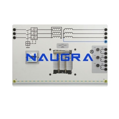
Tramission Lines and Power Transformer.
Electrical transmission lines
The front panel is made in aluminum alloy. Using the
international electrical symbols two models of the line for high
voltage electric power transmission are represented. With
standardized teaching terminals and U-bolts with protection
degree against accidental contacts, it is possible to use the
lines alone or in series/parallel mode. Acting on level switches,
the electrical parameters (resistance, inductance and capacity)
can be changed according to the different sections and lengths
of the line. The presence of voltage is signaled by signaling
lamps, while the protection against overloads is carried out by
quick acting fuses.
TRAINING PROGRAM
The training concerns the study of the three-phase transformer
and the study of the power transmission in high voltage
networks.
Main treated subjects:
• ideal transformer, real transformer
• vacuum tests, load tests and short-circuit tests of the
transformer
• efficiency of the three-phase transformer
• delta, star, zigzag connection and vectors phase
displacement of three-phase transformers
• transformer protection devices
• models of power transmission lines with concentrated
parameters
• voltage drop and losses on the power transmission lines
• kind of lines (copper aluminum)
• parallel of the power transmission lines
TECHNICAL SPECIFICATIONS
A) POWER TRANSMISSION LINES SIMULATOR
The structure is made in sheet steel chemically treated and
painted with epoxy paint; the base is provided with rubber feet
and can be laid over a work plane. The lines are protected
against overload and short-circuit with quick-acting fuses.
Main installed components:
Line 1
Changeable parameter: Section (range in A)
Used line model: PI
Simulated Un: 120 kV Un of work 400 V
Simulated Pn: 10-15-20 MVA
In of work: 1A
Distributed equivalent R: 18-25-35 ohm
Distributed equivalent inductance and capacity: 72 mH,
0.2 micro Farad
Sectioning switches for line start and end
Line 2
Changeable parameters: length (km)
Used line model: PI
Simulated Un: 120 kV Un of work 400 V
Simulated Pn: 20 MVA
In of work: 1A
Distributed equivalent resistance: 8.9-18-35 ohm
Distributed equivalent inductance: 144-72-36 mH
Distributed equivalent capacity: 0.1-0.2-0.4 micro Farad
Sectioning switches for line start and end
Possibility to use the lines in single mode or in series /parallel connection.
Dimensions and weight
Module: 840x450x680 mm – 35 kg
Power supply
3x400 V max. 50-60 Hz
Theoretical-experimental manuals
Manual with exercises
Provided accessories
1 Set of cables and U-bolts with 4 mm safety plugs
B) THREE-PHASE POWER TRANSFORMER
Used as transformer elevator at the output of the production
central station, the output can be connected to the high voltage
transmission lines
power: 1500 VA
primary voltage: 230/400/346 V 50-60 Hz
delta/star/zigzag connection
secondary voltage: 230/400 V with phase variation between
Primary and Secondary of +/-20 electrical degrees.
delta/star/zigzag connection
protection: IP 22
in-built thermal protection
4 mm diameter safety terminals
dimensions: 360x200x300 mm
weight: 19 kg
