- Civil Lab Mechanical Lab Engineering Lab Equipments
- sales@didacticlabequipments.com

CAT NO: DIDACTICECE-LAB-0072
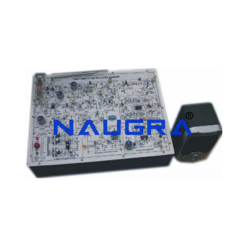
Radio Receiver.
INTRODUCTION
is one of the experiment boards that constitute the
Interactive Practical Electronics System – I.P.E.S.
It consists of a set of components and circuits for performing experiments.
The lessons included in this module can be developed in:
- Standard mode: using the switches of the equipment and
consulting the handbook;
- Computerized mode: the interactive software version of
the handbook - interfaced to the module
via Control Unit , is used. This software inserts circuit
variations and faults automatically enabling the development
of lessons even without teacher’s assistance.
TRAINING PROGRAM:
• Block diagram of a superheterodyne receiver
• Demodulation techniques for AM, DSB, SSB, FM and
logic states transmissions
• Radio (antenna)/cable reception
• Received signal field strength meter
• Received code meter from radio control via Led
• Local oscillator
• PLL Circuit (Phase Locked Loop)
• Frequency synthesis with PLL
• Carrier suppressor regeneration
• Change of tuning frequency
• IF conversion mixer
• IF filter
• IF amplifier
• AGC (Automatic Gain Control)
• Output AF amplifier
• Calibration and measurement of all stages and the
whole module
• Troubleshooting
• System test and measurement
• Use of the spectrum analyzer
TECHNICAL SPECIFICATION:
• AM/DSB receiver in Medium Wave (MW) band
• SSB receiver in 80-m SW band (3-4 MHz)
• FM receiver in Medium Wave (MW) band
• Radio-control receiver in Medium Wave (MW) band
• Decoder: 9 output lines (4 Data lines and 5 Address lines)
• 2 Local Oscillators: manual frequency control (direct
voltage variation) or automatic frequency control (PLL
frequency synthesis)
• Warning LEDs: 2 LEDs for PLL lock, 1 LED for tuning, 1 LED
for valid Coding and 1 LED bar for the intensity of received
signal
• Characteristic of IF/RF test points: low impedance (50 ),
compatible for connection with spectrum analyzer
• MW band tuned receiving antenna of ferrite
• Input BNC connector for outdoor antenna or cable
LF amplifier: power of 1 W with volume control
• Loudspeaker included
• Fault simulation: 10 faults can be inserted
• Interconnection and test points with Ø 2 mm
• Quick changes in circuits via Microswitches
• 37-pin connector for connection with control unit
• 8-way connector for connection with power supply unit
• Printed circuit with protective coating and silk-screenprinted
synoptic diagram
• Module equipped with ABS protection on its lower side
