- Civil Lab Mechanical Lab Engineering Lab Equipments
- sales@didacticlabequipments.com

CAT NO: DIDACTICNEE1049
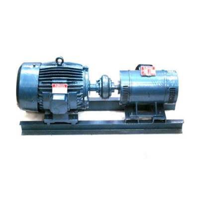
Motor-Generator System.
All wiring connections from machine windings are brought out to 4mm terminals. Connection leads with banana plugs facilitate quick and easy connections between the Motor-Generator System and other controls. A fault insertion for machine winding is available as an optional item for student troubleshooting exercises.
An operation Manual with student experiment activities is provided in English.
Educational Objectives:
Induction motor as prime mover principles
Saturation Curve of Generator/Alternator
Balance Load Effect of Generator/Alternator
Unbalance Load Effect of Generator/Alternator
Open circuit, Short Circuit characteristics
Voltage regulation in Generator/Alternator
Losses and Efficiency in Generator/Alternator
Troubleshooting Generator/Alternator system
Specifications:
Control Panel :
Power supply: 220/380 VAC, 3A.
Power Indicator : indicate the incoming power at L1/R, L2/Y, L3/B.
Power Control : Start Button, Stop Button, Emergency Button.
Lamp Indicator : indicate run, overload and emergency condition on Instrument panel.
Circuit Breaker : ELCB (Earth Leakage Circuit Breaker), MCB (Miniature Circuit Breaker).
AC Voltmeter : Used to measure AC voltage.
AC Ammeter : used to measure AC Current
Motor Switch : used to connect-disconnect the motor with the power supply.
Generator Switch : used to connect-disconnect the generator output to load.
Generator Excitation : DC Voltmeter, DC Ammeter, DC MCB for short circuit protection, Excitation Switch, Excitation Control (%), Variable DC power supply (3 to 180VDC).
Generator.
DC Shunt Wound Generator,
Alternators
1 Ph. Alternator with Cylindrical Rotor, Stator Wound Rotor exited, 300VA
Motors:
DC Shunt Motor, 1 HP
AC Three Phase Induction Motor, 1 HP
Accessories:
1 Set of test leads.
Base plate machine bed with anti vibration rubber feet (bench top type) and protective cover.
Student experiment manual.
Extras:
1-ph resistive load
Faults Insertion System for Motor/Generator winding
