- Civil Lab Mechanical Lab Engineering Lab Equipments
- sales@didacticlabequipments.com

CAT NO: DIDACTICNLE-Export-205120
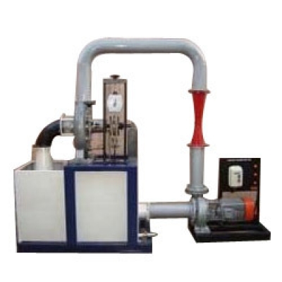
Kaplan Turbine Test Rig
Our organization is regarded among the authentic manufacturers and exporters of optimum quality Kaplan Turbine Test Rig.
Highly acknowledged for its corrosion resistance, shock proof body
construction and hassle-free operation, offered equipment is extensively
demanded among our huge client base.
Description:
Kaplan Turbine is an axial flow reaction turbine named in honour of Dr. B. Kaplan, a German Engineer.
This
turbine is suitable for low head. The power produced by a turbine is
proportional to QH. As the head (H) decreases the discharge (Q) must
increase to produce the same power.
The present set-up consists of a scroll casing housing a runner.
Water enters the turbine through the stationary guide vanes and passes through the runner axially.
The runner has a hub and airfoil vanes,which are mounted on it . The water is fed to the turbine by means of Centrifugal Pump.
The runner is directly mounted on one end of a central shaft and other end is connected to a brake arrangement.
A
transparent hollow cylinder made of acrylic is fitted in between the
draught tube and the casing for observation of flow on to the airfoil
vanes.
This runner assembly is supported by thick cast iron
pedestal. Load is applied to the turbine with the help of drum brake
arrangement so that the efficiency of the turbine can be calculated.
The set-up is supplied with control panel.
Pressure and Vacuum gauges are fitted at the inlet and outlet of the turbine to measure the total supply head on the turbine.
Experimentation:
To study the operation of Kaplan turbine
To determine the Output Power of Kaplan Turbine
To determine the turbine efficiency
Utilities required:
Electricity Supply: Three phase, 420 VAC, 50 Hz, 32 Amp. 4 Pole MCB with earth connection.
Water supply (Initial Fill)
Floor Drain Required.
Floor Area required: 3.5 x 1.5 m
Tachometer to measure RPM
Mercury for Manometer (250gms)
Technical Specifications:
Output Power: 1 kW
Discharge: 1000 LPM
Supply Head: 5-8 M
Normal Speed: 2000 RPM
Dynamometer: Rope Brake type
Water Circulation: Centrifugal Pump, CRI/Standard, Make, Capacity 5 HP, 3 Phase
Discharge Measurement: Pitot Tube with Manometer
Sump Tank: Capacity 200 Ltrs
Pressure Measurement: Pressure Gauge & Vacuum Gauge
Piping & Fittings: Pipes & fittings with flow control valves of suitable size
Control Panel Comprises of: L&;T make Starter, Mains Indicator,MCB for overload protection.
Instruction Manual: An ENGLISH instruction manual will be provided along with the Apparatus
Tanks will be made of Stainless Steel
The whole set-up is well designed and arranged in a good quality painted structure
.
