- Civil Lab Mechanical Lab Engineering Lab Equipments
- sales@didacticlabequipments.com

CAT NO: DIDACTICNLE-Export-096004
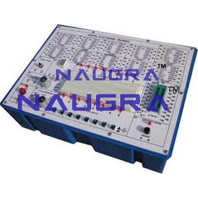
Design And Realize A Given Function Using K-maps For Electrical Lab Training.
Design And Realize A Given Function Using K-maps And Verify Its Performance
Design & realize a given function using K-maps
8 TTL compatible logic level inputs.
Logic HIGH and logic LOW are displayed by dual color LED.
Two crystal generated clock output of 10Hz, and 1Hz.
Facility for single pulse generation by a push button switch.
Logic probe to check logic LOW, logic HIGH and pulse.
One seven segment display with BCD inputs.
Bread board area with facility of more than 1200 TIE points.
Capable of accepting wire diameters from 0.3 to 0.8mm.
In-built Power Supply
User’s Manual, Cables & Connectors.
Housed in an attractive ABS Plastic cabinet with cover
