- Civil Lab Mechanical Lab Engineering Lab Equipments
- sales@didacticlabequipments.com

CAT NO: DIDACTICECE-LAB-0064
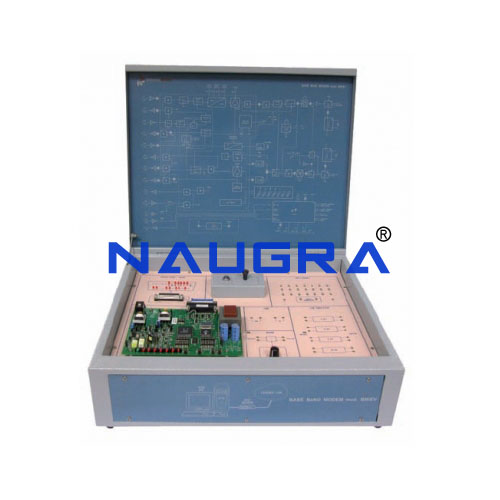
Base Band Modem.
Trainer is a modem designed to examine all the
main aspects concerning the digital modulations and data
transmission on Voice line (Public and Private 2W/4W).
The equipment is assembled in a metallic, compact and
functional box including electric circuits, silk-screen printed
panel with block diagram, test points of easy access, signaling
LEDs, accessory circuits (noise generator and Time Slot
selector), simulator for 16 faults and theoretical-experimental
handbooks.
A complete data transmission laboratory can be assembled
with the main data transmission system and different optional
accessories:
• 2 Baseband Modems form the data transmission
system. Every modem has a serial port that can be configured
as Async/Syncf for the connection of a terminal (e.g.: a PC, if
it is configured as Async).
• 2 Interface testers are professional instruments
for optional measurements
• 1 Data tester is used for measurements and
optional testing (for instance, it can measure BER).
TRAINING PROGRAM:
• International standards
• Modulation and coding techniques
• Structure of network and telephone lines
• Description and operation of serial interface circuits V24
RS232C
• Modem operation and programming
• Waveforms in test points
• Synchronous and asynchronous communication
• Link structure: dedicated line, half-duplex and full-duplex,
2-wire and 4-wire, point-to-point and multi-point
• Control of modem operation, with tests on interface (loop2)
and line (loop3) loops
• Remote loop control according to recommendation
ITU-T V54
• Use of Interface Tester and of Data Tester
• Line and noise effect on the link
• Error rate measurement
• Troubleshooting on device and communication system
TECHNICAL SPECIFICATION:
• Baseband modem according to ITU-T V24/V28 and EIA
RS232C
• Programmable operating speed
• Synchronous and asynchronous serial data
• Full-duplex on 4 wires, half-duplex on 2 wires
• Programmable delay time C105/106 (RTS/CTS)
• Selectable transmission level
• Programmable equalizer
• Fitting ITU-T V54 for enabling local and remote loops
• Artificial line simulator:
- 2/4/8/16-km artificial line
- Noise generator with level control
• Data generator: 2 outputs
• LEDs of state: serial port data and control lines
• Structure: compact box with lift able cover, containing all the
electronic parts, as well as signaling and test points, and the
fault simulator; the block diagram of the circuit is available
on the cover
• Fault simulator: 16 faults can be inserted via switches; unit
protected with key-locked cover
• Test points: 23 test points mounted on a panel and connected
directly with the equipment circuits
Power supply: 230 Vac 50 Hz single-phase - 40 VA
(Other voltage and frequency under request)
