- Civil Lab Mechanical Lab Engineering Lab Equipments
- sales@didacticlabequipments.com

CAT NO: DIDACTICNJC0027
Auto
electric fuel injector model.
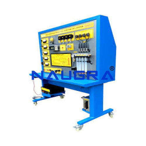
This item is part of the Petrol Fuel Injection Trainers Series. The trainers are designed to train technicians in the operation, theory, maintenance, calibration and trouble shooting of fuel injection systems. It consists of a complete, fully operational, fuel injection system and is complete with a training course on fuel injection system operation and servicing including student job sheets and a technician manual.
Fully functional engine control system is installed in a mobile aluminum frame. This training board-simulator is specially designed to help technical students understand better multipoint petrol injection (MPI) system. The integrated engine control system shows the different operation modes of the fuel injection/ignition system. The training board-simulator is a great educational tool that allows students to learn the structure of engine control system, study its components and operation modes, perform various measurements, tests and other diagnostic procedures. Technical specifications and functions - The integrated engine control system with multipoint petrol injection system (MPI); - Monitoring operation of fuel supply system, injected fuel quantity, spray pattern quality, fuel pressure of the fuel pump; - Fuel pump is built into a transparent tank which allows to see its operation; - The adjustable air flowrate simulator demonstrates the function of the mass – air flow meter and air temperature sensor; - Visible work process of spark plugs; - Easy access for high voltage measurements; - Manual adjustment of the engine crankshaft speed; - Ability to change the air/fuel mixture by the oxygen sensor signal simulator; - The training board has a complete electric wiring diagram of multipoint petrol injection system (MPI); - Electric wiring diagram with built in banana plug jumpers for measurements and simulation of system fault codes; - Ability to simulate more than 20 faults by disconnecting Banana plug jumpers; Diagnostic and measurement Oscilloscope/multimeter - System’s parameters are measured by connecting to the banana connector - Ability to measure electrical signal parameters of each system component (such as sensor or actuator) - Ability to measure high voltage circuit of the ignition system Control unit diagnosis - Diagnosis through OBD 16 – pin diagnostic connector - Electronic control unit (ECU) identification; Reading/erasing fault codes - Displaying the operating system parameters (live data) - Activating the actuators (Depends on the control unit) - Throttle valve adaptation - Control unit encoding/configuration Other - The stand has a closed structure – internal wiring is not visible - Power supply: 12V from the battery or power supply unit (battery and power supply unit are not included as standard accessories)
